
Prevost Community Forums

Find answers, ask questions, and connect with our
Prevost Community around the world.

  • Heart Interface inverter failure

    Posted by Bernard on May 23, 2016 at 9:03 am

    My grandfather called me last week saying that his inverter/charger was acting up on his 1997 XL Elegant Lady. He checks on the bus every couple days, so this happened on Thursday while it was sitting in the shop on shore power. He noticed that the remote panel was not illuminated, even though it was switched on. He started testing the electrical circuits fed by that inverter and when he turned on the battery charger circuit breaker, the line voltage went to 180V and he promptly shut it off.

    I visited yesterday and brought my Fluke. When he showed me what it was doing, we noticed that it tripped the GFI on the outlet above the galley sink when the Battery Charger 2 circuit was turned on. Thinking he might have a short, I tested the resistance between the hot/neutral and hot/ground on that outlet and only read 2 ohms. I did the same in several other outlets, and as long as the breaker was on for that leg, I read 2 ohm. When the circuit breaker was opened, the resistance was 500 ohms for the rear leg and ~800 ohms for the front leg.

    We unplugged from shore power and tested the voltage coming from the shop and got 120V on each leg of the 240V plug. After a call to Troy, we pulled the inverter.

    The DC side was getting 25.6V. The three AC circuits had no voltage, which made sense after the remote wouldn’t power up. The curious part was that when the breaker for ‘Battery Charger 2’ was switched on, the inverter put out 120V on the battery charger circuit and 180V on the AC output circuit. So that verified that the meter in the galley was accurate. I’m not sure why that would trip the GFI though, as I was told that GFI measures potential difference between the neutral and ground. We removed the cover and the two glass fuses on the front board were not blown. After looking at the big board on the side though, I noticed a transistor had blown itself in half. That led me to inspect the back side of the board and I saw several pins were burned out.

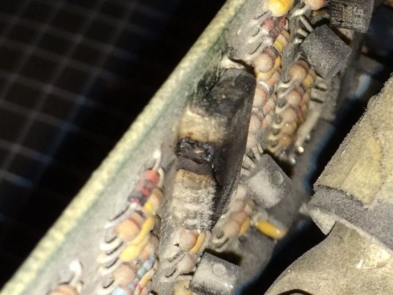
    This component (small microprocessor perhaps?) is also split in half. So it looks like it’s time to replace this with another Magnum MS4024. I replaced the other Heart with this model on 5/20/13, so now he will have both inverters producing pure sine wave power. The previous retrofit required a bit of fabrication to get the cooling air ducted into the invertor. This one has a bit more room to spare, so it should be a little easier. Also, in 2013, I applied some plastic sheet over the crumbling insulation to keep it out of the invertors and heater fan. It has worked well, but that is what all the mess is in the pictures.

    One thing I’m curious about is what checks I can do to the wiring to ensure that this new inverter won’t be compromised after installation. I can certainly check the resistance with the AC wiring disconnected from the inverter and all appliances unplugged from a given circuit Is the low resistance characteristic of being connected to the inverter?I didn’t think to measure the resistance across the AC leads at the inverter after disconnecting. After considering the 180V output measured at the inverter and the GFI tripping, perhaps the faulty inverter was sending power across the neutral wire that was out of phase with the hot wire. That’s just guessing though. I don’t really want to subject the electrical system to that again to find out.

    Also, do the inverters charge the house batteries by sending power back through the DC hookup? Or do they send AC power to external chargers?I didn’t see house battery chargers in their compartment.

    Archived replied 10 years, 2 months ago 6 Members · 6 Replies
  • 6 Replies
  • Archived

    Member
    May 23, 2016 at 11:17 am

    It does look like the inverter is toast. Once you have the dead inverter disconnected, I’d make sure that there is no short in the wiring itself. Disconnect the shore power and check impedance between neutral and ground wire. It should be high as long as you do not run off the generator. Impedance between hot and neutral should be high also as long as no loads are connected.

    It may not be related to your problem but a loose neutral supply connection can cause havoc on a 240V split phase system. Depending on the loads on the split phases almost any combination of voltages from 0-240v are possible on each leg. It would certainly blow your inverter.

    On our ’99 Marathon, the inverters do charge the house battery bank when connected to shore power. I assume it is the same for a ’97 Liberty.

    Gerald

  • Ted

    Member
    May 23, 2016 at 1:41 pm

    Thanks for the info and the additional checks. I will report back after we work on it next.

  • Deleted User

    Deleted User
    May 23, 2016 at 4:12 pm

    If I was concerned about possible damage to the cables or wires I would look at them to see if there was any evidence of heat damage at either end. As long as you have access to the inverter and will be removing the wires you will be able to see them easily.

    It will be worth opening the panel on the electric box and looking at those wires associated with the battery 1 and 2 circuits, as well as the wires to the short bus bars fed power through the inverters. I suspect the short duration of time the high voltage was present did not permit any heat rise or damage, but it is worth checking.

  • Tim

    Member
    May 24, 2016 at 7:52 am

    Sounds good, will do. By electrical box, I assume you mean the breaker panel in the galley and not the panel below the driver’s window. The AC wiring connections in the inverter looked fine, so that’s a good sign.

  • Corey

    Member
    May 24, 2016 at 8:24 am

    Yes, that is correct. The electrical panel can be tipped out a little with the removal of a few screws around the perimeter. If you are sure it is dead for your safety, it would not hurt to inspect the connection at each breaker to make sure the screws are tight. If they loosen that becomes a point where heat can be generated so as long as you are in there it is an easy check.

  • Archived

    Member
    June 6, 2016 at 9:52 am

    Here is inverter #1 that was replaced in June of 2013. I built this air duct since the old one would not fit in the available space. The Magnum is a couple of inches wider than the Heart.

    We got the new inverter installed on Saturday and everything is working. The wiring all looked fine so we wired it up. They forgot to order the remote, so we used the other Magnum remote just to check out the meters and the LED indicated that it float charges and it recognizes the 5W AC minimum load and inverts. I guess the house batteries on Battery Charger 2 must be in good shape because it went right into float mode. The other batteries on the charger 1 circuit absorb charge starting at ~80A if they are taken off of the carger for any length of time and go to float within an hour.

    I was able to re-use the air duct from the heart so that the external fan can draw air through the new inverter. These also have internal fans. I moved the mounting boards towards the rear a couple of inches to accomodate the wider Magnum, but other than that, it was a straight-forward install.

    Thanks for the advice everyone!

Log in to reply.