
-
Electrical Problem after wiring move
Posted by Robert on December 26, 2011 at 6:38 amHi Folks
I am far along on a process of changing a seated coach to a motorhome. In that process, one of the things I needed to do was move the voltage regulator and batteries to the rear of the coach from the 4th bay. I was successful in getting that done but the final outcome is still a problem. Everything worked well before moving electrically speaking but after the move, the headlights act crazy. On low beam, both are normal but on high beam the left healight goes out completely. The second issue is when watching the dash mounted voltmeter, it was stead as a rock at 27 volts before the move but after the move, the needle jumps back and forth from 26 to 28 every second. Natually, the lights dim and increase with the change in voltage. Jon and Bob on this and other forums have helped me find the wiring diagrams from the prevost site and I hooked the batteries/wires up according to the diagram as best I know how. Any ideas besides starting over and rechecking all the wiring one wire at a time?
Rob
91 Prevost XL 40
Missouri
Rodger replied 14 years, 8 months ago 11 Members · 26 Replies -
26 Replies
-

Rob,
Something changed when you rewired.
Without pulling your wiring diagrams I have some free thinking about places I would look. First, your headlights are 12 volt so pay special attention to how the battery cables have been connected. Your batteries are set up to provide both 12 and 24 volts, and the equalizer is there to maintain the relationship between both voltages.
Your 12 volt side should be exactly 1/2 the voltage of the 24 volt side plus or minus 1/2 volt. I would start by verifying that under various conditions, such as engine running, engine off, lights on, lights off, etc. Apart from lights the 12 volt side is critical because it is the power source for DDEC.
I don’t know if this applies, but Prevost had a service bulletin at one time that modified the wiring in the front box because when the headlights were turned on or went to high beam (I cannot remember which) it caused a voltage drop that was affecting DDEC. It would be worth checking voltage at the lights and at the terminals for the lights in the front box. If the 12 volt supply is marginal DDEC may be affected. I have no clue how to check to get access to the service bulletin. Maybe Prevost is on here now and can jump in and answer.
-
When you moved your batteries did you use a new frame ground.? Also when you extended your feed cables 24 &12 volt did you use kern connections or other brass/bronze/copper? On the headlights they feed thru one side to the other and a low voltage or weak/corroded connection can cause the second in line to be starved by low voltage supply. I know you are a elect guy so in this case just like putting a resistance in line. Back to the battery install. Sure sounds like Grounding somewhere and that might fix everything in guestion. If you used jumper post in rear engine compartment for ground verify its integrity/put a pair of pliers on it and try to pull it loose. Just food for thought. Best wishes and let us know what you find. Bob
-
Check the equalizer to be sure there is less than 1/2 a volt between the 12 and 24 terminals and be sure your cables are hooked properly, it’s easy to miss one when dealing with series/parallel.
-
Bob
Yes, when I moved the batteries, I used the chassis ground back by the starter rather than the one in the battery compartment in the 4th bay. It is used for the starter and the engine case ground so I thought it should be fine. I do not know what a kern connection is but I used an aluminum connector that you slide the bare cable into each side and then tighten a screw down on the cable since the cable is #6 wire. I was concerned since the original cable that I cut to extend is copper and the new cable is aluminum. Don’t know, since I am not an electric guy, if theis dissimilar metals would cause this kind of problem but I doubt it. I suppose the connections could have corroded but it is only been two weeks since the lights worked normally and I then embarked on this project. I will check the voltages but I think it must have been something I did or didn’t do that caused the problem, especially since it has been only two weeks since everything was normal. Speaking of grounding, the ground wire off the voltage regulator has two branches, one to 4 relays next to it and one to the old substation above where the batteries used to be. The one cable that goes to the substation has 3 branches on it. One of them goes to old chassis ground in the battery compartment and two that attach to the old battery substation. I have found the location for one of the ground wires on the substation but there is one ground wire branch that I have no idea where it goes. I have looked at the diagram and it only shows one location for the ground wires on the substation. That is how I have it hooked up now but it clarly is not working. I would post a pic to show you guys what I am talking about if I knew how to do so. I did use the + booster block to run power forward to the 24 volt cutoff switch leaving it in the original position rather than moving it also but all I did in that case was move the wires from one post to another, nothing else.
Rob
91 XL 40
Missouri
-
Rob,
To post a picture hit reply and a box will drop down for you. You know how to do that so the next step is to look to the left of the you tube box and you will see a picture of a tree with the sun. Click on that and a new box will drop down. Click on upload and go to your photo library via the box that drops down, select the photo and click “open”. In a few seconds it will load in the box
Click Okay and the picture will load on the post. Click on POst Reply and it will show up.
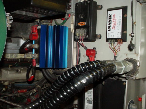
In my picture the blue thingy is the isolator, the voltage regulator is to its right, the monitor which lights the annunciator bulbs on the dash is to the right of the regulator, and below the AC hoses with the white label is my equalizer. The batteries are below that. The circuit breakers and the master switches for the chassis are in the lower right corner of the photo with only part of the 12 volt master switch partially visible.
-
Just posted long reply hit post ;it dumped it so will simplify. Got you mixed up with Steve on Jobs: Kerny-looks like slotted bolt with nut one end over lap wire about 2 inches = almost 0% loss connection next to welding. If you disturbed your shut off switch. ck supply and delivery sides there-when these old guys get disturbed a little the get out of their wear pattern and loose surface area contact. Check your voltage in front drivers side compartment (upper) and compare to supply at rear. Need full 27.5 running. Vanner deals with multiple voltages and systems so will have multiple grounds. You are using two I think? Lights feed thru Curb side to drivers if I remember correctly. Low voltage would so up dovn stream on a dc system(dim light). I really think your looking at a ground problem. goood luck finding your ghost. Bob. I’ll be running it thru my feeeeble mind in the mean time. keep us posted.
-
Guys
I am still checking into the voltage issues but I did take some pics so you could see what I am talking about.
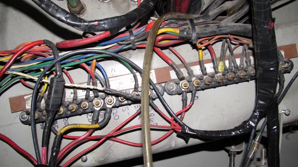
This is the substation (junction) in the 4th bay I was talking about. There were several connections in this junction and various wires going to relays and some to the voltage regulator. What I did was take the wires off one at a time and then write the number below the lug where it was to go. The one to the far right is number 20 and is the ground wire from the regulator. You can see new looking black electrical tape in front of this junction. Those are the newly extended wires that came from the new battery postion in the back of the coach to the junction.

This is the schematic for the junction. Below is the legend for this junction.

I did remove the wires 3B, 2C, 31A, 45B, 2D, 57, 57A, 47, 122 and 123 becasue they were for OTR air which is not in my coach. I did remove Relay 31 since it went to the water valve for the heating system. I plan to place a smaller pump in later to handle this. Otherwise all I did was match wire for wire. That is why I am crazy for why this is not working.
More pics to follow
Rob
91 XL 40
Missouri
-
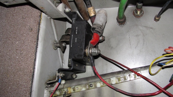
24 volt cutoff switch still mounted in the 4th bay where it was originally. The only thing I did was remove a cable running from the + terminal of 3rd battery to the off position of the cutoff switch and move it to the + booster block in the back curb side compartment next to the engine. I also switched the heavy cable with the red shrink wrap from the off terminal to the on terminal.

This is a pic of the voltage regulator (VR) in it’s new position in the curb side engine compartment attached to the fender skirt. The black wire coming off the VR is the ground wire and runs to the relays to the left of the VR and then runs forward to the junction mentioned in the previous post. The wires run forward and attach at the terminal number 20 on the jucntion. The 12 volt block in the lower leg center of the pic has a bolt head protruding through the back side of the wooden board that everything is mounted on so when I installed it, I put plastic spacers behind the board so the head did not touch the metal fender. That was how it was installed in the original location in the 4th bay. At the very top of the pic are the dual vanners, the left one powering the ATEC and headlights and the right one for everything else. Below is the new battery box I welded up and attached cables to. You can see, I made many new cable due to bad corrison on them before. In the very center of the pic, you can see 3 cables coming from the top down, those are the cables from the vanners mounted on the ceiling of that compartment.

-
Jon
When you get a second, can you use my coach number, M-1839, to find the wiring diagram. Bob sent me a link to one that I used to wire the batteries and I have looked myself a couple of times but I want a 3rd opinion as to which one to use. Not trying to say Bob is wrong since I see where he got it. If you could do that and send me a link, it would be much appreciated.
Rob
91 XL 40
Missouri
-
happens all the time. By your your serial # that is the way I would have started. We were looking for a starting point. Do wish you luck.I hate electrical ghost. Usually turn out to be something unrelated and simple.. No offense taken from me for I understand I learn something new every day. Do share outcome.
-
Progress sort of. Went back out to the coach, wiggled the wire going to the headlight, bing on it came, apparently just loose connection because it has worked since then repeatedly. However, the surging votlmeter continues. I did check voltages. The 12 volt vanner reads 12.56, the 24 volt vanner reads 25.1 volts with engine on or off. The headlight voltage on the passenger side is 11.86 and on the drivers side is 11.74. Don’t know where else to check as I rechecked the battery connections and all the wires I spliced, all look fine. I did notice the surging was less with the lights off but when I turned on the lights, the surging worsened and it is definately noticable when looking at the headlights/marker lights/tail lights. Anyone have any ideas, let me know.
Rob
91 XL40
Missouri
-
just wonder if this wire is also feed to some functions in front pannel yellow = 12 volt feed in this system your 12 volt is reading low with your 25 plus on 24 side the 12 should read 1/2 of that Again looking for ghost ? you don’t have 1 weak battery? or one with bad cell. If they are over three yrs old might even need to low test. I had one with bad cell once that screwed whole system up. might also ck breaker (12 volt)
-
Interesting Rob you have a seated coach and I have a MH 91XL40 M-1838
Greg
Is there a way to save the font size you want to use, instead of defaulting to 12px?
-
His 12 vs 24 is dead on, 12.56 & 12.55. Half of 25.1 is 12.55, so the equalizer is doing it’s job.
-
Breaker? good catch on vanner I had read the 11 figure at lights and feeble mind was thinking at front junction box. Why drop between front junction box and lights? bad or weak breaker? corrosion ? bad ground/loose wire on post in pannel. hot or ground. Had a ghost that we searched for for months and turned out to be loose nut on post. one 1/2 turn could have cost thousands dollars shop time.( caused low voltage to ddec and engine would die) keep me straight guys Bob
Log in to reply.