
-
Do I need my battery equalizers?
Posted by Chad on May 11, 2017 at 10:42 amThis 1984 Liberty Coach (96″) is still new to me, and I’m learning the systems as I go. I have two Vanner battery equalizers installed in the engine bay. One is a 60-50A and the other a 60-50, and they are apparently installed in parallel. The 24v/12v/Gnd terminals of each are tied to the other. What I can’t figure is why I have them? My chassis has two 12v 8D batteries installed in series, but nothing is pulling 12v off of just one of them. My house bank is 12v, but I’m reconfiguring that due to limited space where it currently lives. I read the Vanner documentation, and I think the installation is pointless if you’re not pulling 12v from one of the chassis batteries. I certainly don’t understand having two tied together.
Two additional bits of info. First, there is what I think is a relay that sits between the 12v terminal on the 60-50 and the chassis cut off switch. That cable from the 12v terminal is the only one I see that doesn’t lead to the other Vanner or the +24/Neg terminals of the chassis batteries. The other alarming fact is that the 12v terminal of each Vanner is actually showing 25.X volts to ground, just like the 24v terminals.
I’m guessing someone butchered the setup somewhere down the line. Assuming I’m not missing something fundamental here, does it make sense to just remove the Vanners, or is there a benefit to correcting the installation?
1984 96" with 8V92TA
(remodeled Liberty Coach)
Greenwood, MOTim replied 9 years, 4 months ago 14 Members · 20 Replies -
20 Replies
-

You’re certain there are no 12v device needs correct? Later vintage with DDEC has to have12v, but you’re pre DDEC I assume.
-
You absolutely need them, even though you have a mechanical engine. Your coach has both 12 and 24 volt requirements and the equalizers are maintaining the relationship between the 12 and 24 volt circuits in your battery bank.
-
Thanks for the replies. I have a pre-DDEC 8V92-TA Silver. I’m sure there are 12v needs, but I’m fairly certain the equalizers aren’t meeting them. Not only are the +12v terminals on both equalizers putting out 25-ish volts, but the only cable coming off the +12v terminals to something other than the other equalizer is running to the load side of a relay that goes to the main bus electrical cut off. It looks like that relay is controlled by something in the engine electrical compartment, but I haven’t chased it down yet.
1. Shouldn’t I get 12 volts to ground from the +12v outputs on the equalizers?
2. What would the 12v outputs typically go to? I’m wondering if someone shifted those circuits to the 12v house bank at some point. I can’t think of anything electrical that isn’t working right now.
I’ll dig into my maintenance manuals to see about 12v circuits on the chassis, but I’m feeling a little stumped at the moment. Fortunately this sort of troubleshooting is actually enjoyable for me, and I always learn a little or a lot!
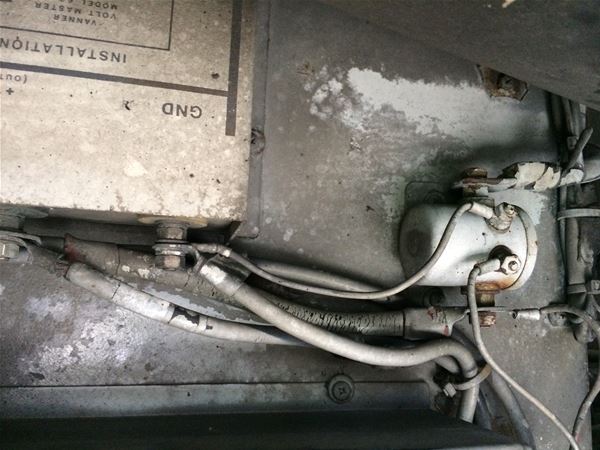
This is the 60-50 feeding what I think is a relay?
-
Trying to answer questions about what might have been done by a previous owner is impossible. There have been so many examples of stupid mechanic tricks posted on this site and others we know people who make changes because they are smarter than the engineers who designed the bus are an endless supply of stupid.
I have no clue what your specific coach has as far as 12V requirements but it has some. So to answer your question about voltages, at the terminals on the equalizers you should have 24 volts (nominal) between the 24V post and ground, and 12 volts (nominal) between the 12V post and ground. The 12 volt reading should be one half of the 24 volt reading within 1/2 volt if the equalizer is working properly.
-
Thank you, Jon. I double-checked today and I have about 24.6 volts to ground at both the 24v input and 12v output of both equalizers. No surprise that the two equalizers are the same since they’re wired in parallel. I spent a few hours poking my head over and around my engine in order to map out the wiring in my engine compartment. I may never be clean again. Everything looks good except for the equalizer setup. I’m going to isolate them on Monday to see which one is throwing 24 volts out of its 12v output. If only one is bad, I can at least hook the other up correctly. I also might post my hand-drawn electrical diagram for comments and suggestions. I want to make sure everything is proper before I invest in new house batteries. The last set had been cooked and were bulging when I bought the coach. I’m patched together with a 12v car battery so I can use my generator, but have no real capacity.
-
Okay, I see what is going on here. I didn’t realize that the 12v output on the equalizer could be used to charge the house 12v battery bank. I saw all of the diagrams where that 12v output went to the middle of two 12v batteries wired in series for the 24v chassis electric. Of course I have 12v circuits in this old gal! So this setup allows me to charge the house batteries (and power my inverter) when the coach’s engine is running without firing up the generator. That will certainly come in handy. I still need to determine the cause of 24+ volts on the 12v output, but the problem seems more manageable now. Here’s the section I had overlooked in the Vanner manual:

Thanks for prompting me to think through it.
-
You mention the use of the equaliizers to charge the house batteries and power the inverter when the engine is running.
That suggests strongly someone has changed your coach from its original configuation at some point because your vintage coach I don’t believe ever had inverters originally. Also I am not sure what you mean when you say it can power the inverter. An inverter is either going to charge a battery bank when it has AC power input, or take power from the battery bank when there is no AC power input. Your equalizers are “hot” or working whether the coach is running or not. That means if your house is connected to your equalizers you are going to be tie the house and chassis batteries together and you not only are charging them at the same time, you are draining them both at the same time. I would expect to see a relay or solenoid somewhere in that line. I would expect the battery banks would only be merged when the engine is running and the relay or solenoid closing only when the engine is running.
-
Regarding the inverters, I have only used DC to AC inverters in the past. Inverters that can use AC to charge a battery are new to me. I have two Crown automatic marine converters that look original, and a single 1750w inverter that was obviously added later.
I probably muddied the waters when I said the equalizers can power the inverter. I was surprised to learn that the equalizer can charge the 12v house batteries from the 24v system while the engine is running, which would be nice. I’ve had to run the generator in my current configuration to run even light AC loads. I’d love to run a Cruisair once I upgrade the batteries and the inverter. The Prevost OTR air is great for everyone but the driver (greenhouse effect and minimal airflow).
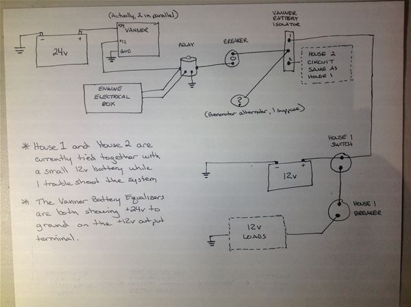
This is what I diagramed yesterday, minus some additional 24v stuff that I decluttered. You’re right about the relay:
-
Vannerr tells you the output of the 12 volt terminal should be exactly 1/2 of the 24 volt reading. If it is not exactly 1/2 replace the Vanner. They also tell you to disconnect the ground first and connect it last when removing wires. If you have 2 Vanners in parallel you have to disconnect to check the other one then reconnect and disconnect the other one.
-
Here is a link to their testing procedure. http://www.vanner.com/manuals/65-80.pdf . However their procedure is fairly long. The 12 volt reading should be 1/2 of the 24 volt reading with all connected. Test it as you would like.
-
Thanks again for the information. I checked voltages with the engine running and found 26.6/13.3 volts on the 24v in and 12v out terminals. The 24+ volts only show up on the 12v output terminal when the engine is off. I haven’t learned if this is by design, but it doesn’t appear to be an issue because (as Jon mentioned) the 12v system is isolated by the solenoid when the engine is not running. Based upon this, I didn’t bother isolating the equalizers. They don’t appear to be a problem. I also went ahead and installed new 12v deep cycle batteries in the house circuits.
I was surprised to see that the 13.3 volts didn’t reach the house batteries with the engine running, so
I tracked it from the equalizers. The Vanner battery isolator is showing 13.3 volts on the center terminal, but just the battery voltage on the two outer, battery circuits. I can’t find much info on this device (model 50-140), but the Vanner brochure specifically says it allows the batteries to be charged. This suggests it should be passing the 13.3 volts through to the two battery circuits.So far the solution to each of my “problems” in this thread has been to learn more, so I’m open to the idea that I am missing something else here. Any thoughts on the Vanner Battery Isolator not passing the 13.3 volts to the battery terminals?


Log in to reply.