
-
Shore power/inverter/Techlink issue
Posted by Doug on June 21, 2013 at 11:23 amThis is my first post on PC, I am familiar with a few of the members here from the BCM forum. I have already learned a lot of good information here in the few weeks I have been reading posts. I did a extensive conversion of a 1992 MCI 102C and enjoyed a couple years of great trips. In Oct 2012 I purchased a 2001 H3 Marathon from Marathon Coach in TX and sold the MCI about a month ago. I was pleased with the people and experience at Marathon and spent about two full days looking over the coach. I have had no real issues since we got the coach but have only managed to get away for four short trips.
I recently started having a issue with the electrical system where the AC loads appear to be drawing power from the batteries while on shore power. When I got the coach and up until a few weeks ago, the “normal” condition when on shore power with no large AC loads running, was the inverter remotes on the meters menu and the techlink screen showed the batteries being charged. Now the remotes and techlink show a small current draw on the batteries with only the fridge running, when I kick in a AC for instance, the techlink screen will show about 13 amps AC current being used on the phase the load is on, but unlike before it will also show DC current being used from the batteries, from 20 to as much as 65 amps or more if I run multiple AC’s.
I should mention here that when I got the coach that I was aware the house batteries were approaching end of life. I replaced the six batteries with new lifelines the end of April this year and everything was still normal after that. The problem started when I re-connected to shore power one day after having the coach pulled out of the garage for about 6 hours and running off battery power. However while unplugged there were no AC loads to speak of and the batteries appeared still near full charge.
I have a service appointment with Marathon in TX on Monday to have it looked at. I have done troubleshooting over the phone with their electrical guy who seems knowledgeable and familiar with the system but we do not seem any closer to a diagnosis. Any input or experience would be appreciated.
Bryan replied 13 years, 3 months ago 9 Members · 28 Replies -
28 Replies
-

Are you sure you are getting Shore power? What happen when you run the generator?
-
While making a effort t keep the initial post brief I did leave out some important details.
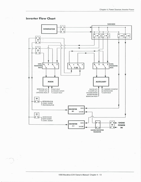
Yes I do have shore power, tested it with meter and the problem remains on other shore power sources as well. The inverters are Trace SW4024 and they are set to 50 amp shore cord and 50 amp grid. The remotes indicate shore power not inverter power. Everything is normal when running the generator. The power system in the H3 is quite different from my previous coach where the shore power fed the main AC panel which fed the inverter which fed the AC sub panel for inverter loads. On the Marathon each phase of the shore power feeds a inverter which feed the main and aux AC panels and certain loads are disconnected by load management transfer switch in the absence of shore/gen power. My manual only has a shore/inverter power flow diagram but not a complete schematic so I am not certain how it all works. The generator appears to feed the main and aux panels directly through the transfer switch and not through the inverters so it would make sense that the inverter is not transferring from battery power to shore power correctly when on shore power . Like I said I am having Marathon look at it on Monday but I am the type that likes to understand the problem before I let someone else try to fix it.
Hoping I could get some insight here before I go in on Monday.
Thanks
-
Doug,
Let me take a stab at what you have.
You have commercial and generator power feeding an automatic transfer switch. The selected transfer switch output is then feeding the inverter/charger. The 4024 supports a comemrcial and generator input. So, I have to assume only the commercial input to the Trace is in use. If this is correct, let’s move on.
The AC1 Good LED should be solid when the incoming AC has been both detected and accepted. It will flash when the input is detected but not yet accepted. My guess is that when commercial power is applied and the generator is off that the this LED is either off or flashing. It would most likely be off. If off then the commercial power is not making it through the automatic transfer switch. If true, then it would most likely be the detector circuit in the transfer switch is there isn’t a tripped breaker between the transfer switch and point where you are measuring the incoming voltage.
Okay, I just reread what you said and am in a bit of disbelief. If the transfer switch is after the inverter/charger then the generator can’t run the charger. It would seem unusual for anyone to bypass the battery charger when you have a more than capable generator. The previous paragraph still applies with respect to the LED indication.
-
Doug,
Keep in mind there are a lot of ways to set up our coach electrical systems, but one thing is a constant no matter how the electrical system has been set up by the converter. That constant is the system will be logical.
I may be wrong but I would have guessed your shore and generator inputs pass first through a transfer switch, with the transfer switch giving priority to the generator. Then that power goes directly to the AC panel. The inverters would then get their power via the AC panel for battery charging and likely the inverter circuits such as outlets, refrigerator, one or two AC units, etc.
But my viewpoint is that of a Liberty owner so none of what I said would be information you would want to bet on. Your description however seemed to suggest the shore power relay in the transfer switch is not passing power as it should. But my opinion on that matter ain’t worth much.
-
Jon and Gil
You may be right and what you described is exactly how I set up the system in my MCI. Here is the drawing from my Marathon manual and it appears to me that the gen power does not go thru the inverters. only a 30 amp feed to supply charging power and power to the fridge and microwave circuits which appear to be before the shore/gen transfer switch.
-
You are correct in that Marathon utilized external transfer switches in the 1st or 2nd bay wall to feed the interior load center panels (Labeled Main and Aux), but there are dedicated breaker panel input breakers from a panel labeled Shore Load Center, and Gen Load center (bay 1 or 2) to feed each separate AC1 and AC2 input of the Trace SW4024 inverters. The generator inputs to each inverter are only 30-amp breakers for the charging function of the inverters ,and the loadcenters inside the coach are fed “around” rather than through the inverters when on generator power via the transfer switches, while the Shore input DOES go through the inverters and these breakers are 50-amp. This allows for the Shore Cord setting to be of consequence for loads in the Main and Aux Panels in the bedroom. The Aux Panel is controlled by a contactor in the bay and is “kicked offline” if Shore Cord power draw goes over 53 amps or if there is no Shore or Generator power present, so that this panel is not powered by the inverters. This is done to prevent overloading the shore cord or help prevent overloading the inverters.
You should look at the “AC1 in Good” lights on each inverter remote while the shore cord is powered on. As long as these lights are on, the breakers for the Shore Power input to each inverter is present and not tripped. They will be accompanied by either the Bulk or Float light, telling you what state of charge your batteries are in. Next thing to check would be the 35-amp round white breakers on the left side of each inverter. These are the charging or invertering breakers and are inline with the transformer in the inverter/charger. They do not effect “pass-through” of the contactors, only power flow into or out of the transformer towards or from the batteries. These can occassionally get tripped if the inverters are overloaded while inverting.
After that, I would check the Setup Menu settings for Menu’s #9-14. If the Max Charge Rate is too low, the inverters won’t be charging your batteries, if the Shore Cord Amps (or AC1 in Amps) is too low, you could actually be inverting to run loads, even while plugged in to 50-amp service.
Some other situations that could cause actual battery discharge while plugged in involve the inverters not being “happy” with the shore power or battery voltages. If the cord voltage the inverter “sees” is below 105 or above 140 volts AC each inverter will not connect with the shore power, as indicated by the AC1 IN Good light flashing rather than being “on solid” green; or if the battery temp-compensated voltage is high, the charger setpoints are automatically adjusted down, and could not be charging the batteries, but actually be inverting to lower battery voltage to compensate for high battery temperature.
Hope this helps.
Sincerely,
Ben Cummings
Parliament/ Coachworx
-
Doug,
If you don’t know Ben Cummins, he’s an expert on the electrical systems implemented by the converters. What ever he says you can take to the bank.
Your wiring diagram is interesting. It shows some out-of-the-box thinking on the part of Marathon. They certainly could have simplified what they did and saved themselves some money. So, I looked at what they did and tried to understand why. First, the good news is the drawing and Ben confirmed the generator does charge the batteries. I didn’t see in the inverter manual where the generator input was limited to 30A. If it is, what Marathon did was out of necessity, again I didn’t see a 30A limit on the generator input. What they did achieve is the ability to keep your coach powered in the event the inverter’s internal by-pass relay or or incoming AC voltage quality monitoring circuits fail. If either fails, just start the generator and all is well. This maybe what you’re experiencing now and something Tom just experienced last week. In Tom’s case, the systems powered through the defective inverter could not be powered at all, in your case the generator can be used.
-
Good job Ben and Gil,
I had a short conversation with Leon last week up at Coburg about what can be done in the case of a major failure and how to get back and powered up. I had a hard time grasping the way Marathon wired their bus and could not understand. It’s alot clearer now. Thank you.
Later
bv
-
It’s interesting that the main and aux panels change from one being 30 Amps and the other 50 amps on shore power and change to 50 amp and 30 amps on Generator. Does this mean that anything on 50 amps doesn’t work while on inverters?
-
After a closer look at the drawing, I don’t get what’s going on. The critical loads being powered on the 2 30A breakers off the inverter must be powered by both the generator and shore power through the inverter or its by-pass relay. So, why wrap the rest of the generator power around the inverter? Why are these 2 30A critical load breakers outside the Main panel? The Main panel is powered by all power sources. Maybe, Marathon kept the critical load 30A breakers separate as an easy way to extend dry camping time by letting the owner simply turn off the Main 50A breakers. In any case, the external transfer switches do nothing in offering a way to power critical loads in the event of a by-pass relay failure in the inverters as I originally thought.
-
That is not unusual Gil, and in the event of a by-pass relay failure in the inverters if the inverters are easily accessed as they are in most coaches, all you have to do is connect the inverter input wires to the inverter output wires with some wire nuts and the circuits are powered via shore power or generator.
If you don’t have accessible inverters or don’t wish to monkey around with wires if one fails, installing a by-pass switch is an easy addition.
-
After physically tracing some of the wiring and looking at the drawing it is pretty much as Ben said. However even though the main shore power breaker is 50 amp, the breakers in the shore load center box that Ben mentioned are 60 amp, that feed the Main and Aux panels. The breakers in the Gen load center panel are 50 for the inverter feed and 60 for the Aux. There are no 30 amp breakers in the Gen load center but there are 2 30 amp breakers in the main panel labeled inverters which does not seem to match up to the drawing. If those are the breakers feeding the inverters when on gen power, then it looks like they would also be doing it when on shore power. I am sure it’s not a case of the Aux panel not being kicked in because those circuits still work, it’s just when I turn on a AC load the remotes and the techlink screen both show a big load on the batteries
I have verified both phases of the shore power at 122 volts, checked the cord amp size and the AC1 grid amps both set at 50. checked the charge rates and the high and low voltage settings for the inverter input, and have a continuous green light on the AC1 in .
It is not shown on the drawing but in bay 2 near the inverters in addition to the disconnects between the inverters and the house batteries, there are inverter 1 and 2 bypass switches labeled Shore/Normal/Generator which I think is to avoid the wire nut scenario that Jon mentioned.
I am leaving for Marathon in Dallas in about a hour but will check back in late this evening to see if anyone has any additional thoughts. Will post their findings once they have it figured out.
Thanks
-
Gil,
I was referring to the last sentence in your post. I’m not qualified to discuss the specifics of Marathon’s or any other converter’s systems.
Log in to reply.