
-
Installing Inverter?
Posted by Richard on April 7, 2014 at 2:15 pmI am in the process of researching the do’s & don’t’s of an inverter in my Liberty coach. I guess Liberty was not yet installing them in my year model, therefore, I don’t have a pre-wired system I can wire to.
My selector switch doesn’t have the option so I will need mentorship regarding the switch and how the inverter is wired into the rest of the system. I am fairly familiar with how it works and I am not afraid of hands on installation, I just don’t want to mis-understand the needs and the switching side of it.
If my main selector switch has shore, generator and off, can the off selection be used for inverter or should there be an off selection for everything?
I plan on running LED tv’s, refrigerator, sattelite, some lighting etc, but didn’t think an A/C unit would be run from the inverter, for that I can run the genset.
Thanks for any guidance or feedback.
Richard
Greg replied 12 years, 7 months ago 10 Members · 19 Replies -
19 Replies
-

Richard,
One thing to be sure of when installing an inverter is to keep those circuits powered from the inverter isolated from shore or generator power.
With the switch you describe you should have an “off”, “shore power” and “generator” position. I suspect you may also have a 4th position for the inverter, but if not you need a switch that will support the inverter position, or a means of isolating the circuits powered by the inverter from the others and thru the electrical panel a means by which you can run 120V to (and thru) the inverter.
If you are comfortable with electrical circuits this will not be a big deal, but if you are not, take the coach to someone that is.
The hardest part will be running wires from the 120V panel to and from the inverter.
I think what you are doing is a great idea and not especially difficult, but a lot of things have to be considered to avoid problems, all of which can be very serious and even dangerous if not avoided.
-
Richard,
Forget the switch, it’s meaningless to your inverter project.
How much house battery do you have?
Can you locate the inverter near the house batteries? Keep in mind you will probably toss your current house battery charger and install an inverter that also has a charger. The inverter/charger may fit in the same space.
You may need to run AC wiring from your main AC breaker box to the inverter depending on the guage of wire already run to the charger and whether it will reach the new inverter/charger. You will need an AC breaker box for your inverter loads and a way to wire from the inverter breaker panel to the inverter loads. The easiest way is take those wires out of the main breaker box and divert them to the new inverter breaker panel.
PM me if you need more details.
-
Gil,
That switch on Liberty coaches of that vintage is in lieu of a transfer switch. Unless he has added a transfer switch which makes the project much more complex he needs to retain it. Otherwise he is going to have phase issues.
-
I’m interested in this too. My Vulcan conversion does have an inverter. Bruce doesn’t like automatic switches, so in my power bay I have a big breaker that says generator and a big one that says shore. I just pick the one I want. I have a switch by the driver to turn the inverter on and off. I run the inverter with the generator all the time. Do I just switch to shore in the bay and leave the inverter off when plugged in? I figured I would still need it on…
-
Jon, I didn’t say he should remove the manual transfer switch, just that the switch is meaningless to his project. If a common inverter/charger is used they have an automatic transfer switch built-in.
-
Dale, I hope you can’t physically turn on both the generator and shore breakers! I suspect it’s like many boats where only one breaker can be on.
What does the inverter switch actually do? Maybe it controls a inverter transfer relay? Regardless, the inverter switch shouldn’t function differently whether you are on generator or shore power.
-
In my mind I am thinking the inverter would be powered by the house batteries and feed from the inverter to the selector switch that would have a selection for inverter. From the switch, it just feeds the power to the breaker panel right as the other selections do right? I need to understand how the inverter is wired into the house batteries as I know all my 12 volt lighting etc is also feeding off of the same circuit. If my thinking is right, I would prefer not to complicate the installation any more than that unless there is something I am not seeing.
What is a reliable brand and usable wattage I can research for the coach? The range of cost can be hundreds to thousands depending on just the brand…. Please advise.
Thank you
Richard
-
Richard,
What do you want to power from the inverter(s)? I am going to assume you will be using a xantrex, magnum, or other common invertet/charger.
Creating a 3rd power input; shore, generator and inverter is technically possible but it would be a big mistake. To do so requires you to physically turn off all AC loads that exceed the capacity of the inverter(s). Don’t do it!
-
Richard,
Your inverter would be fed 120V through the electric panel when shore or generator power was available. When that was the situation your inverter would function as a battery charger for your house batteries, and 120V power would pass through the inverter (from shore or generator power) to the circuits in the electrical panel you choose to be powered via the inverter.
When shore or generator power is not available, the inverter would draw power from the house batteries to provide 120V power to the circuits in the electrical panel.
Those inverter circuits must be isolated from the other circuits in the 120V panel.
I agree with Gil that the inverter can function as its own transfer switch in the absence of shore or generator power, but I am concerned that a rapid on-off cycle of shore or generator power due to a variety of reasons could outpace the inverter ability to switch and that could create a problem so you have to decide if you want to add a 4 position master switch or stick with what appears to be your 3 position switch.
Do some research before you jump into this by looking at inverter installation methods and wiring diagrams. This is not something to be slapped together.
-
Just for technical accuracy. Only a combined unit that has an inverter and charger in the same case would have 120V AC as an input. The AC input is solely for the charger. BTW, I would recommend a combined unit for space and because they have a transfer switch incorporated in their design.
As for the quickly cycling AC input from shore or generator power being a problem, it is a power problem that you want to avoid regardless on whether you have an inverter.
Again, you do not want a third position on your manual transfer switch for inverter power. Look at the drawing on page 9 of this document. It should help you understand how the inverter should be wired in. This assumes, and I assume, you will be using an inverter/charger.
FWIW, I used the Magnum manual only for its illustration. I do think they make a good product, but there are others. All would be wired the same.
-
Thank you for the diagram, it helped clear up some questionable issues I was thinking about. I have to assume that while plugged into shore power, it passes through the inverter to supply power to the sub panel and the inverter is merely charging the house batteries. I am wondering where my subpanel will have to be located, as y’all know, space is limited in the present power panel.
You guys are great, you just don’t know how much I appreciate your mentorship and feedback. Just two weeks ago I was literally broke down with an air problem and y’all got me going again. Thank you.
Sincerely
Richard
-
Richard,
Here is an over simplified functional diagram of an inverter/charger. As you should see, there is a transfer relay inside the inverter/charger. It is triggered on the AC input and is fully automatic. You can manually control the inverter and charger functions, if you would like, but they default to automatic. The only inverter chargers that are different are those that can augment available commercial power. In coaches, that would be a Trace 4000.
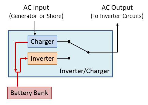
You can put the sub panel where ever you want. What will drive that decision is ease of wiring and available space. These subpanels can be quick small, maybe on the order of 8″x8″. If you want to reuse existing ciruits, you will likely want the sub panel near the current master breaker. Although even that’s not a given and for me to suggest the best placement without seeing your coach and what you want on the inverter would simply be a SWAG.
-
On the Liberty align the inverter circuits by moving the switches and labels around so they are all on one leg of the bus bar behind the panel.
Then cut the bus bar so it’s supply comes from the inverter and not the big black knob controlled power supply. It is the wiring routing to and from the inverter that will be an interesting part of the job.
-
You need to realize an inverter is power service point. As such, it has its own neutral and it bonds neutral and safety ground together. Therefore, the transfer relay inside the inverter/charger must switch hot, neutral, and safety ground.
Your manual selection switches should also be switching both hots, neutral and ground.
If I’m reading Jon’s post correctly, I don’t recommend that approach. If you did you would also have to lift the nuetral and grounds from the bus bars they are attached to and connect them to the inverter power. I also assume you don’t want to power everything on one leg of the two from the inverter. So, you can’t just divert the power from one leg to the inverter. The inverter’s transfer switch can’t take the extra load and the inverter can supply enough power.
-
Gil
I assume the manual selector switch does switch both hots, the neutral and the ground. Don’t know, never took one apart.
What I described was how the inverter powered the 120V panel on my previous coach with two hots and a neutral. I oversimplified stating to cut one bus bar. The inverter output did not have a ground so I presume the neutral and ground were bonded. My point is by relocating the existing circuit breaker / switches to the bottom of a bus bar all needed is to separate those portions of the bar from those circuits not powered through the inverter.
Log in to reply.