Prevost Community Forums

Find answers, ask questions, and connect with our
Prevost Community around the world.

  • AC Analog Panel Meters

    Posted by Archived on December 16, 2011 at 8:01 pm

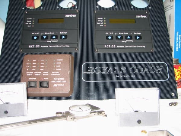
    I’ve not has any issues with regard to AC amperage, no matter how much I loaded up both legs. The problem, is the analog gauges are unreliable and never get above 15 amps AC. I put my Fluke on the hot side of each leg at the electrical panel and the actual amps were almost twice what the meters would show. So I started taking things apart and decided to replace both the volts and amps meters, at least for a nice cleaner look. One of the old volt meters was in poor shape on the backside of the barrel anyways.

    After searching for a few days I found meters that would fit, the barrel dimensions had to be just right to fit the existing holes and the installation was a breeze. Unfortunately, the new meters didn’t fix my low amp reading, not a big surprise and I learned why at a very good electronic shop near home. My transformers are in the AC electrical panel in the bedroom and the meters of course are above the dash. The transformers are good and reading the correct amps. The problem is the wire run to the front of the bus. The shop did some calculations for me and the drop in amps is caused by approximately 30′ of wire that reduces the meter needle deflection to about 1/2 of the actual amps being used. Great design Royale, I can’t believe no one in the past noticed the 20 amp readings when just about everything in the bus was running and both AC legs were just about to the 50 amp max each.

    So, if you have lazy amp needles, you may have the same issue. My plan is to add digital meters for the amps and locate in the galley where it’s easy to monitor.

    Finished Panel
    Old Meters Removed

    John replied 14 years, 8 months ago 7 Members · 18 Replies
  • 18 Replies
  • Archived

    Member
    December 17, 2011 at 6:39 pm

    Tom,

    That’s a strange problem and I suspect it has been there
    since the coach was built.

    Amp meters generally measure 0 to 5 amps when located remotely.
    The amp meter is matched to a standard donut transformer on the leg to be
    measured. You probably have a 100 to 5 transformer meaning that it will supply
    5 amps to the meter when 100 amps are conducted through the wire passing
    through the donut hole. In order to have a ½ reading you would need to have a
    200 to 5 donut transformer or a 10 amp meter.

    A common method of doubling the amperage created by the
    donut transformer would be to loop the wire back through the donut. This should
    correct the problem and double the amp reading you currently have.

    I do like the idea of a digital meter. You will have a clear
    indication of how unbalanced your circuits are.

  • Archived

    Member
    December 17, 2011 at 8:20 pm

    John,

    My transformers are 50.5 and matched to the meters, old and new. I couldn’t loop any wire due to space restraints, so I’m kind of stuck. The tranformer wires are 14 gauge as well as the home runs to the front of the bus. What do you have since our Royale’s are pretty close?

  • Archived

    Member
    December 18, 2011 at 8:33 am

    Tom,

    John is correct, you should be able to loop either the primary or secondary wire to compensate for your problem.

    This link may helphttp://www.alliedelec.com/Images/Products/DataSheets/BM/SIMPSON_ELECTRIC/Simpson-Electric_Industrial-Control_9180009.pdf

    Cant seem to paste link, button is greyed out. Perhaps you can help Tom

  • Ron

    Member
    December 18, 2011 at 11:53 am

    Tom,

    I will go to the barn and see what size wires are on my Royale
    after the Titans game. My initial reaction would be the wiring to the meters is
    oversized based on a maximum current flow of 5 amps so no problem there. The
    wires carrying the current through the donut hole to the distribution panel are
    way undersized. Normally I would expect a 14 gauge wire to be rated at 15 amps.
    The thought of pushing 50 amps through a 14 gauge wire should melt the
    insulation.

  • Archived

    Member
    December 18, 2011 at 4:52 pm

    Tom,

    I hate to admit it, but I can’t find the donut current transformers on my coach. Were are they located on yours?

    It appears that I have the same gauge panel you do. Figured it was easier to ask than take everything apart.

  • Archived

    Member
    December 18, 2011 at 8:38 pm

    John & Lee,

    The donuts are mounted properly on the heavy gauge wire for leg 1 and 2, the 14 gauge is the wires coming from the donut all the way to the gauges. That appears to be the problem due to the excess distance. There is no way to get extra loops through and around the donut unless I add additional heavy gauge wire to leg 1 & 2 and I don’t want to do any splicing. Besiides, it’s all so tight in the electical box, I doubt I have enough room.

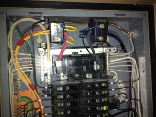
    The donuts are mounted inside the electrical box in the bedroom John. They are mounted in the top of the box with the leg 1 & 2 running through them. It’s really tight in there, not much room. I also had to relabel some breakers due to changes made in the past and got everything sorted out and properly labeled. I’m glad I tackled the project because now I know everything is correct in the panel.

  • Bob

    Member
    December 18, 2011 at 9:26 pm

    Tom,

    I thought the current transformers might be in there. Just lazy and didn’t take the
    breaker cover off. I disagree that the 14 gauge wire is the problem unless it’s
    been damaged on the run to the front. The current to the meters should be a
    maximum of 5 amps. That’s 1/3 of the current a 14 gauge wire is rated for. Suggest
    you take one of the meters and connect it to the transformer with a foot of
    wire in the bedroom. That should verify or eliminate the wire as a problem. I believe
    you said you had an Amprobe type clamp on current meter. You should be able to
    use it to measure the current to the meters
    .

  • Archived

    Member
    December 19, 2011 at 6:11 am

    John,

    The wire gauge is not the issue, according to the guy at the shop, the distance to the meters is just too long. He did a calculation using 30′ of 14 guage wire and told me I’m losing about 50% of the value by the time it gets to the meters. I have a Fluke to check the amps. I hooked up one of the meters at the electrical panel directly to one of the donuts and it matched my Fluke. I had 25 amps going, so I then hooked the meter back up front and it was about 50% less.

    I’m not an AC expert, so if you come up with a solution, I’m all ears.

  • AL

    Member
    December 19, 2011 at 5:29 pm

    Tom,

    Put a heavy load on the shore power today and didn’t get a current
    reading over 30 amps which verifies your readings. I haven’t paid much attention to the amp
    readings because I have not had any problems and my interest was in balanced
    current draw. I removed the circuit
    breaker panel cover and took a look at the current transformers in my coach.
    The installation is probably identical to yours. I discovered what I believe is
    incorrect wire routing. The transformer secondary wires pass through the
    primary loop hole in the donut current transformer.

    The secondary wiring should not pass through the primary loop.

    I have seen one of the secondary wires used to fine tune the
    current on large applications. Don’t recall the ratios used but I’m reasonably
    sure that one of the secondary’s added to the primary loop will increase the
    current and the other one will decrease the current.

    I have never seen both secondary wires pass through the
    primary loop. I’m not sure what the affect is and didn’t have time to change
    the routing to see what the change would do.

    Remember that I’m a Mechanical Engineer and will probably
    assume the power is OK if there is no smoke or fire and Jons not helping, based on experience at Prevost Nashville.

  • Michael

    Member
    December 19, 2011 at 5:50 pm

    John,

    My transformers are a little different, but the wires do not go through the donut hole on mine, they go directly to the meters. You would think we would have identical setups since they’re both 97’s, but maybe someone changed one or the other out over the years. Wish Ben was on here, he could shed some light.

  • gary

    Member
    December 19, 2011 at 9:36 pm

    Tom,

    If you loop the white wire from the transformer back through the transformer you can change the output signal thus changing the reading on the gauge.The link below likely explains it better than me.

    http://www.alliedelec.com/Images/Products/DataSheets/BM/SIMPSON_ELECTRIC/Simpson-Electric_Industrial-Control_9180009.pdf

  • Archived

    Member
    December 20, 2011 at 5:29 am

    OK Lee, so I take the white secondary wire and pass it through the donut on the way to the meter, correct? That appears the way Johns is wired, but his has both wires running throught the donut by the looks of the picture.

    Thanks…

  • Archived

    Member
    December 20, 2011 at 6:47 am

    Tom, Yes that is correct. You are trying to induce more current into the transformer. This will help make up for the lose due to resistance in the cable to the meter. It will take quite a few wraps depending how far off you are. If you are off close to half it is easier to wrap the primary wire once and then fine tune with the secondary.

    Your other option is to buy a Liberty!

  • AL

    Member
    December 20, 2011 at 7:30 am

    Liberty? That was harsh!

  • Bob

    Member
    December 20, 2011 at 9:01 pm

    Tom,

    Im going to have to bow out on this till after the hollidays. Flying back to LA in the morning, back in 2 weeks. Still plan to be on line but won’t have the coach to play with. Hope you can solve it so I can fix my amp meter when I get back.

    Photo is close to home 50 miles from LA @ 6500 ft in the Angeles National Forest. No the coach can’t get there.

Page 1 of 2

Log in to reply.